Valve Cover Access Modification
In order to adjust the valves on the MP3 400, you have to remove all the upper plastic. Anyone who has done this will tell you what a PITA that is. It's worse for me because of my topcase mounting bracket, auxiliary tail/brake light wiring, and side case brackets. Some hardy souls have adjusted their valves by removing only the side access covers and belly pan, but from their descriptions of the process, it sounds just as difficult as pulling all the Tupperware.
My solution was to cut the fuel tank cover and the front of the saddle base/storage-area pan so that those parts can be easily removed to access the valve cover. It was a lot of work, but now that it's done, I can remove those parts in a just a few minutes and not have to mess with the rest of the plastic covers at all. Here's the procedure, in case anyone else wants to do it:
Preliminary Disassembly
Remove side access covers, belly pan, backrest, passenger grab handles, taillights, rear cover, rear upper side covers, rear lower side covers, and central cover.1 (This is what you normally have to do to every time you need to adjust the valves!)
Fuel Cover
- Separate the three main parts of the central cover: left front cover, right front cover, and fuel-door assembly (fuel cover).
They are joined on the inner side with screws and a pair of clips.2
- The central cover's front arch and upper sides overlap a recessed lip on the bottom of the fuel cover.
Note the line that demarcates this lip, and mark it on the inside of the fuel cover.
- Fabricate a set of metal brackets3 with their midpoints along the marked line,
each bent to fit the angle of the planes at its station.
Every pair will be unique, but all will have two 1/8" holes for pop rivets and one 3/16" hole for a screw (Figure 1).
Number the brackets and their places on the cover.
- Using the brackets as templates, mark the rivet holes on the lower lip of the fuel cover.
Drill and attach the brackets with Clecos (Figure 2).
- Using the brackets as templates, drill screw holes into the upper part of the fuel cover.
- Remove brackets.
- On the outside of the fuel cover, countersink the rivet holes so the pop rivet heads won't protrude (Figure 3).
Use a 1/4" pilot-point bit, drilling backward. Drilling backward is important!
If you drill forward, the bit will cut all the way through the plastic before you can say "Oh, @$%#!!!"
 Figure 1 |
 Figure 2 |
 Figure 3 |
- The front of the fuel cover contains the fuel-door hinge mechanism and should not be cut. Mark it accordingly (Figure 4, left).
- Cut off the lower sides of the fuel cover with a Dremel or similar.
- Rivet the brackets to the sides and put "speed" clips on the upper ends of the brackets (Figure 5).
 Figure 4 |
 Figure 5 |
- Normally, a screw at the front of the fuel cover holds it and the two front halves of the central cover together.
After this modification, the screw will still fasten the cover sides, but the front of the fuel cover will sit below the screw head.
To create clearance, make a dimple by heating a similar screw (Figure 6) and pressing it into the front lip of the fuel cover (Figure 7).4
 Figure 6 |
 Figure 7 |
- Assemble the two halves of the central cover and attach the fuel cover lower sides.
Saddle Base/Storage-Area Pan
- Remove the saddle, rear upper frame, and helmet storage cover.
- Remove four large Phillips screws from the front of the saddle base/storage-area pan.
- Mark the bottom of the pan from the aft corners of the access cover hole outward.
Prop as necessary, and cut with a Dremel or similar as shown in Figure 8.
Remove the front section.
 Figure 8: Rubber edging has been applied to the cut ends. |
Preliminary Reassembly
- Install helmet storage cover and rear upper frame.
- Install central cover assembly.
- Install rear lower side covers, rear upper side covers, rear cover, taillights, passenger grab handles, backrest, etc.
- Cut holes in the central cover to provide access to the saddle mounting screws (Figures 12 and 13, upper- and lower-right corners).
The holes won't be visible when the saddle is closed. You can tape over them to seal out dirt.
Raison d’Être
Now you can adjust your valves! I found it helpful to drill a 1" hole in the right footrest to access the #1 valve cover bolt (Figures 9–10). A plastic plug covers the hole nicely (Figure 11).
 Figure 9 |
 Figure 10 |
 Figure 11 |
Saddle Base Installation
- Remove a pair of sheet metal screws anchoring the central cover sides (not pictured) aft of the cut line.
Carefully spread the upper sides of the central cover to allow the back end of the
saddle base/storage-area pan to slide into place.
- Fit the ignition coil into the front of the saddle base and secure it to the bottom of the pan with two large Phillips screws.
- Replace four large Phillips screws to anchor the saddle base.
Fuel Cover Installation
- Remove gas cap.
- Slip the front lip of the fuel cover under the front arch of the central cover. Attach the fuel door cable.
- Swing the back end of the fuel cover downward and tuck its ends under the central cover. Replace gas cap.
- Secure fuel cover with sheet metal screws. Replace two sheet metal screws in central cover.
- Install saddle.
Finally, install the side access covers, belly pan, and any other fiddly bits I might have forgotten to mention.
Figure 12 shows the fuel cover and the front of the saddle base/storage-area pan removed. Naturally this provides access to lots of other parts besides the valve cover. Figure 13 shows everything buttoned up, but with the saddle not yet installed.
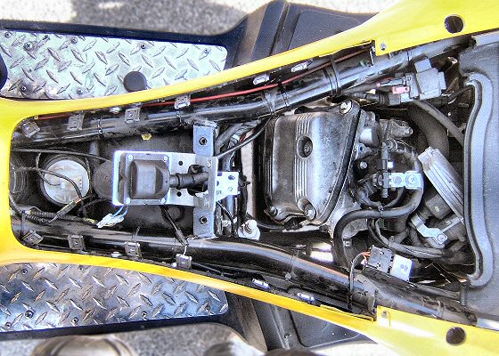 Figure 12 |
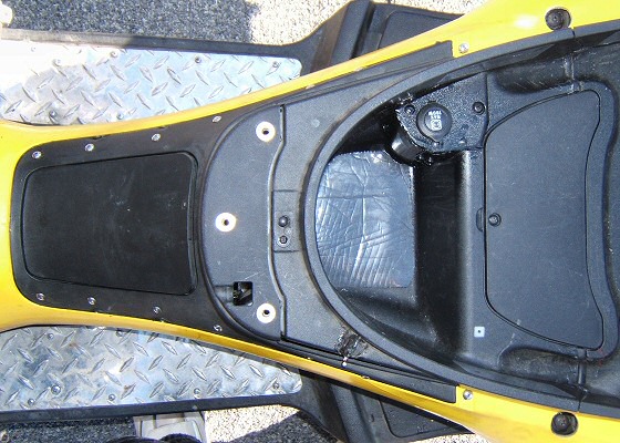 Figure 13 |
Removing all the body covers as prescribed took me more than an hour and lots of swearing. Replacement is similar. With this modification, removing and reinstalling the adapted fuel cover and seat mount, seat, and miscellaneous covers and connections takes less than 15 minutes.
1Some minor steps omitted, such as removing the dome-light switch and storage-area pan
access cover, disconnecting the fuel-door cable and power socket, etc. Also omitted are the seat
"nanny" switch and the evaporative canister, which I tossed long ago.
2I couldn't get the clips back on, and switched to screws.
3This modification uses 12 clips, made from 1/8" aluminum stock. You could use fewer clips, and
make them from sheet steel.
4Or drill a 1/2" hole.