Increasing Front Legroom
Introduction
The thing that bothered me most about the Element was its poor front legroom: Of the seven 2004 vehicles I seriously considered, the Element had the least, 41.0". It wasn't a disqualifying factor, partly because the headroom is so impressive, and partly because the best spec in the group was only 1.6" greater.
I bought the E and love driving it, but legroom continued to be a factor, especially compared to my Rambler's. A little research revealed two important facts.
- The front seat mount hangs over a ledge where the floorboard rises by about 2" (hence the rear "theater seating"), so you can't simply drill holes in the floorboard and move the seat mounts back.
- Honda, presumably fearful of liability, is zero help in solving this problem.
New Seat Tracks
I decided to buy a set of tracks so that anything I did would be reversible. Also, having the modified tracks ready would minimize vehicle downtime.
Honda won't sell just the track assembly. You have to buy the entire driver's seat base, which also includes the pan, springs, and height adjustment mechanism. Honda p/n 7289226, Frame, L., 81536-SCV-A51, $256.73 + tax. I bit the bullet and ordered the base.
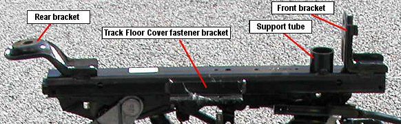
Figure 1: Stock track assembly (inboard view)
Track Modifications
After the part arrived, I removed the left and right track assemblies (two bolts and a spring each) and drilled out the solid 1/4" rivets (four on the left side, three on the right) that secure the front and rear mounting brackets. The front and rear brackets are welded to the track assembly. I removed them and took the parts to a local welding shop.
Not having stock steel U-channel to match the outer track, the welder built up a 3" extension with flat stock. He butt-welded the extension to the front of the track, then attached the front bracket to the extension. (The first time, he put the front bracket on backward; it does look right that way.) The rear bracket was relocated next, and the process repeated on the other track.
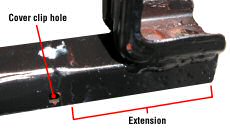
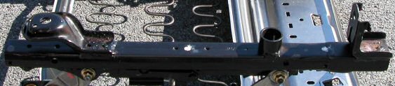 Figure 2: Modified track assembly (outboard view) |
Figure 2 shows the front bracket at the end of a 3" extension; the rear bracket has been moved 3" forward. Note that the front support tube has not moved. You may choose to reposition it, or else use another weight-bearing structure in its place. The Track Floor Cover fastener bracket (visible in Figure 1) also remains where it was—this would haunt me later.
Making Room
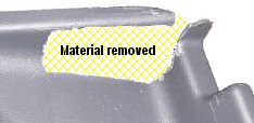
I had to eviscerate the Track Floor Cover (Figure 3) to make way for the relocated tracks and their extended travel. This part of the project was unduly laborious, because it took a million cuts before I appreciated how much material had to be removed. One might choose to live without the Track Floor Cover and just put it on a shelf with the unaltered seat tracks. Either way, barefooted passengers behind the driver will be at increased risk.
The Door Sill Trim also took a small hit, losing one of its anchors (Figure 4).
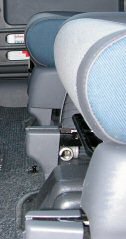
There is a large, slotted, stainless steel tab behind the right track; this had to be bent downward a bit to make way. I also removed some rubber blanket and insulation behind the right track (Figure 5).
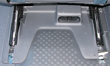 Figure 3: Modified Track Floor Cover |
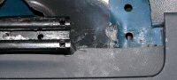 Figure 4: Door Sill Trim cut |
|
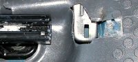 Figure 5: Stainless tab depressed, blanket/insulation notched |
Installation
The Honda technical service manual (TSM) has clear instructions on removing the seat. If your car has front side air bags, do not fail to disconnect the battery. Having an air bag deploy accidentally can ruin your day.
With the seat out of the car, remove the following:
- "recline knob" (a plastic lever cover)
- "recline [left] cover"
- "height handle" (a knob)
- "center [right] cover"
- "slide lever" (a bar)
- the track assemblies
Once the new track assembly, side covers, etc., are in place, it's time to reinstall the seat.
- Remove the Door Sill Trim to allow better access to the left rear bracket.
- Reconnect the cables under the seat.
- Position the seat, and shim the rear seat bracket with washers—no more than 1/4"—to allow a crucial bit of clearance for the left track.
- Screw in the four seat mounting bolts (I used slightly longer bolts in the rear), but do not tighten them yet.
-
If you have not repositioned the front support tubes, affix an appropriate weight-bearing structure under the tracks, just behind the front brackets. I used galvanized iron pipe tees, secured to the front brackets with zip ties (Figure 6).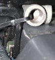
Figure 6
CAUTION: The front track brackets should only have to hold the seat in place; the support tubes bear about half the weight of the seat and occupant. If they are not moved forward when the extensions are welded onto the seat track assemblies, the support tubes will be suspended in midair instead of resting on the frame. Left uncorrected, this condition can apply severe stress to the front seat bolts and the frame extension welds, and could lead to catastrophic failure. - Torque the seat mounting bolts: front, then back.
- Reinstall Door Sill Trim.
- Reinstall Track End Covers and what's left of the Track Floor Cover.
Errors and Lessons
 |
|
| Figure 7 |
 |
|
| Figure 8 |
|
Conclusion In the end I gained a smidgen over 2" rather than the planned 3". As it stands, the improvement is tremendous. You can see the difference in maximum rearward travel between the left and right seats in Figure 9. If I were to do this again, I'd remove the front and rear brackets from the rails, have the rails welded to lengths of steel square channel, and then weld the brackets to the new channel. That would eliminate worries about a possible failure in the butt welds, plus alleviate some of the cutting I had to do on the plastic panels. |
|